Another byproduct of the Operational Amplifier presentation I did for a recent MN-ARTS meeting was to produce a design and PCB for a Op Amp based audio filter. The first prototype I did was a 4th order Chebyshev Bandpass, but as I ran the designs in the TI FilterPro Desktop software, I settled on the smoother Butterworth response to account for CW QSOs slightly off of a 250 Hz boundary.
The schematic below is the design normalized for common resistor values. the TI FilterPro software has the nice feature that it pins the C values to something common, then varies the R values accordingly. Various options are supported to make the BOM and implementation less idealized. The design point was 650 Hz center frequency, 100 Hz 3dB bandwidth, and a 10 dB voltage gain.

KiCAD schematic
The two-layer PCB that resulted was simple and designed around 100% through-hole parts. I sent this to OSHPark like all my other prototype designs. The TL972 or MCP6022 Op Amps are excellent, inexpensive choices for an audio range active filter as both are low noise/low distortion parts. The PCB was designed for flexibility in it’s use and that is why the audio and power connections are oriented to wires rather than jacks.

OSHPark PCB
The designed gain achieved 8.9dB as a real circuit. Using the FilterPro software, any 4th order active filter, single-ended Bandpass topology will work, regardless of response type and the desired voltage gain. The intent of this design was to provide an add-on for homebrew or purchased rigs with insertion into either the audio chain, or directly driven at low volume levels when used with an amplified external speaker.
The Bode plot of the gain and phase below was produced using a Analog Discovery module by Digilent. The WaveForms software used with the Analog Discovery includes a Network Analyzer virtual instrument (similar to NI LabView). The actual response tracked closely to what was predicted by FilterPro.
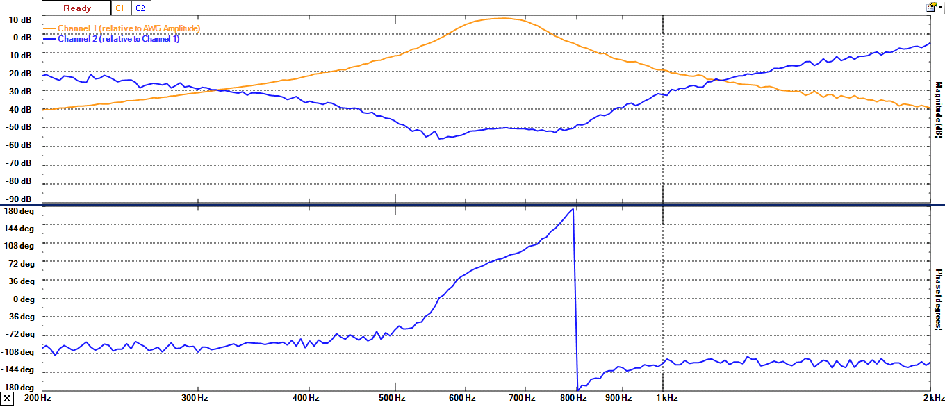
Magnitude and Phase from 200 Hz to 2 kHz
There’s enough of a roll-off with just a 4th order active filter to produce excellent results. With the current design point, any kind of receiver (DC, Super Het, SDR) architecture works once the signal has been demodulated to audio.

I have been looking for simple 100-200hz cw filter kit.to add to TenTec Century 21. Haven’t found one yet that doesn’t have amplifier. Is your pcb available to reproduce on oshpark or do you have some extras? I should have all the caps and resistors, but not the op-amp. Ebay has a 2-pack for $6.99. I’m not sure what the Oshpark board order will be, having not used that service. Allpcb will cost about $24 for five if I can get gerbers from you. Please let me know what you can do for me. Thanks, Dale KS4NS
Typical price on OshPark for this board (3 copies) is pretty low. Here’s the share link: https://oshpark.com/shared_projects/sCq4vfLd
Got the boards. C5 is on the board, but not on the schematic. What is the value of C5? Thanks, Dale
.1 uF Joe.
Hello! Looking at putting your filter into my uBITX. One question… what is the value of R1, 9.1k or 91k? It looks to say 91k, but I was wondering if maybe the decimal got lost in image conversion or something, since the 9 and 1 are pretty spaced out… and R4 seemed sort of a parallel value at 8.2k.
Thanks!
-Rob KC4UPR
Hi Rob, it is indeed 9.1k.
Great, thanks! I actually had also QC’ed it via this site ( https://www.wa4dsy.net/robot/bandpass-filter-calc ) by plugging in your values, and got about the same. Might be useful for trying to adjust the center freq, I’m thinking I may want 700 or 750 Hz. uBITX seems to roll-off on the low side.
FB, I actually used TI Filter Pro to generate the design values, so it should closely agree with other such tools.
Schematic errors. Check the opamp pinouts.
The pinout is correct, here’s the datasheet https://www.ti.com/lit/ds/symlink/tl972.pdf?ts=1614695475097&ref_url=https%253A%252F%252Fwww.ti.com%252Fproduct%252FTL972 check on page 3.